Navigators Model Railway Group
Established 2013 with more than 150 years experience!
Modifying Single and Double Slip Points for DCC working
This article applies specifically to Tillig ‘Elite’ points which I am using on my layout, but the principle can apply to any manufacturers Single or Double Slip points where either some rails are not powered (typically the blades, as some manufacturers rely on the blade contact with the stock rail), or there is a high potential for shorting of the rails because the space between opposing rails is insufficient for the flange width of some locomotives or rolling stock.
The principle of converting points to run with DCC is to ensure that all rails are powered, including the frog, but the frog should be electrically switched according the route selected, whilst at the same time being isolated from the rest of the point, thus eliminating any possible shorting between rails caused by wheel flanges touching both rails.
The fundamental modification to standard points for DCC operation is to extend the area of the frog by cutting through the closure rails and re-bonding to the frog to avoid shorts, plus linking the blades to the stock rails. Although dealing with slips is a little more complicated, not least because in the case of the inner blades they are a part of the frog, the principle remains the same.
Let’s start with the Double Slip as this is in some respects simpler to deal with than the Single Slip.
The inner closure rails on Tillig Double Slip points are one piece and bonded to the outer stock rails by jumpers underneath the sleepers. There is a potential shorting location where these closure rails encroach on the centre cast guide rail, so the answer is to cut through each of the inner closure rails and make the now unattached ends part of the frog assemblies (see Fig. 1).
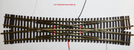
Fig. 1
Having separated the inner closure rails, two jumpers are soldered across the centre guide rail and then each of the free ends of the closure rails (see Fig. 2).
The point blades adjacent to each frog are not powered on these points, so a second set of jumpers are made up and soldered across the centre of the frog and the two point blades in each case.
Finally dropper wires are soldered to the inner and outer stock rails and one each to the frog, which will be connected to the polarity switch of the point motor.
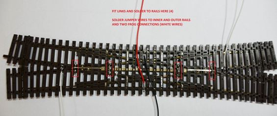
Fig. 2
Applying the same principle to the Single Slip, the inner closure rails are cut half way along their length (to provide as much support on the sleeper chairs as possible after they are cut – see Fig.3).
The centre guide rail, or Slip stock rail, is also a potential shorting location with both the nearby closure rails and the frogs, so this is also cut through before then electrically reattaching the remaining parts to maintain continuity.
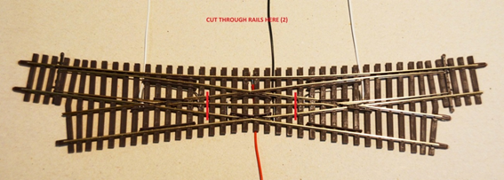
Fig. 3
In the case of the Single Slip, only one jumper is required to re-bond the non-slip closure rail on one side of the points, as an extended dropper soldered across the stock rail and the remaining closure rail will serve to retain continuity on the other side.
As before, the point blades adjacent to each frog are not powered, so jumpers are made up and soldered across the centre of the frog and the point blades and then extended along the point to relink the unconnected closure rails in each case (see Fig.4). This jumper will not cause a problem to the support of the points if foam underlay is used.
Finally dropper wires are soldered to the inner and outer stock rails (the inner dropper extended as described) and one each to the frog to be connected to the polarity switch of each point motor.
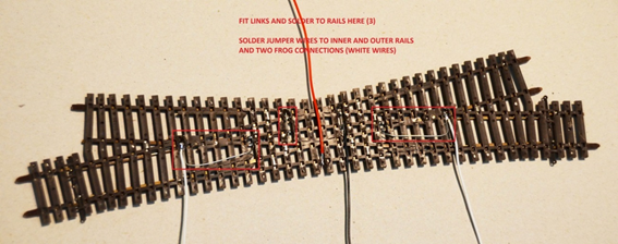
Fig. 4
There is a fair amount of cutting away of sleeper supports underneath the points to accommodate the jumpers and dropper wires. Because a lot of heat is required to ensure a good soldered joint to the rails, it is difficult to do this without melting some of the plastic, but none of this will be seen once the points are in place and ballasted, particularly as the dropper wires are soldered on the underside instead of, as is more often seen, to the side of the rail positions.
Acknowledgement:
Many thanks to Brian Milligan for producing this article. As always this article has been prepared with the intent to help others who may be considering modifying single and double slips for DCC operation. We do not profess to be the Oracle and do not take any responsibility for any damage / failure or losses in whatever form arising from this article.